Software Design/Construction -- Week 3
Introduction
This week we will look at object oriented design.
Note that the links from this page are to handouts that will be distributed the night of class. Only print out those handouts if you could not attend class.
Main topics this week:
Assignment 1 Due
Object Oriented Design
Identifying Objects
UML Modeling
Next Week
Your compiling and debugging assignment is due today.
Why should we use object oriented designs?
Some advantages:
Some disadvantages:
The advantages of object oriented design only apply to well designed systems. It is possible to use object oriented techniques and come up with a design that has none of these advantages. You must keep the advantages in mind and use good design techniques to achieve them.
What is object oriented design?
Uses Objects
An object oriented design will, obviously, use objects. A well designed object is:
Uses Inheritance and Polymorphism
An object oriented design must use inheritance and polymorphism. A design that uses objects but does not use inheritance and polymorphism is called "object based", not object oriented. An object based design does not have all the advantages of an object oriented design.
You should all have seen these techniques in CS II, but we'll review them quickly here.
Reading a problem statement and identifying objects is the first step in an object oriented design. The basic steps to doing this are:
Inheritance and Polymorphism
To make a first pass at using inheritance and polymorphism, go through the problem statement and identify "is a" relationships. These will usually become inheritance relationships between classes. For example, if "F is a G", then G is the base class of F.
Inheritance is not appropriate for an "is a" relationship which is not permanent as far as the application is concerned. For example, if the application must keep track of employees, some of whom are also teachers, then "employee is a teacher" is a temporary is a relationship and inheritance should not be used. You'll also hear this referred to as a "role".
The key points in your student manual describes the use of CRC cards as a way of organizing all this information. You should give CRC cards a try, but remember that you need to use a technique that works well for you.
On large projects, a great deal of design is done before anyone starts coding. This design must be discussed and reviews among a project team that may be anywhere from two to twenty people or more. There are many ways to put designs on paper for discussion. UML is one popular way, and the way that we'll use in this class.
UML Class Diagrams
You've already done UML class diagrams in CS II. A few things to note:
UML Use Cases
A UML class diagram captures a view of the objects that is static. There's no action in a class diagram. To explore the action in an application, we can use UML use cases. Note that use cases are a tool for exploring and refining the requirements. You are not expected to know everything you need to draw a use case just from doing the class diagrams. As part of working on the use cases, you will identify new areas of the design and may need to go back and modify your class diagrams.
A use case represents the desired behavior of the system as seen by the actors. An actor can be the user, or some other system that your application interfaces with.
Use cases start out at a high level, and then become more detailed as you explore the requirements of the system. You include behaviors that are relevant from the point of view of the actors involved (remember, we're exploring the externally visible behavior of the system).
The two primary components of a use case diagram are actors and use cases. Actors are all outside the application, and use cases are all inside the system. We draw the use cases that the actor would normally see as circles. Each circle also has a detailed description of what the actor sees.
We can begin to capture some of the commonality in the system by allowing one use case to use another use case. One use case can also extend another use case...extending is a bit different here than in Java. If use case A extends use case B, then that means that A is something that may conditionally happen when we attempt B. A must also be something that is visible to the user.
Note that the basic use case diagram represents something called the "basic course". This is the user's normal interaction with the system, assuming no unexpected errors. All use cases "used" by a use case are also part of the "basic course".
A good basic tutorial on use cases can be found at http://www.zoo.co.uk/~z0001039/PracGuides/pg_use_cases.htm .
(do example based on ATM interaction)
UML Sequence Diagrams
Okay, you've done the class diagram and the use cases, and are pretty sure you understand the requirements of the system. You're ready to start designing your class interactions for each use case. This is the point where you figure out if your classes can actually do what you want them to do with the methods and data members you've given them.
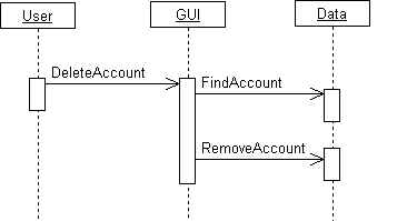
A sequence diagram is, basically, a diagram that shows the sequence of method calls from object to object. Vertical lines on a sequence diagram represent objects or actors, and horizontal lines represent method calls between objects. Time is represented by a progression from the top to bottom of the diagram.
While sequence diagrams can become quite complicated, you can use the basic idea to explore object interaction. For example, here's a sample that describes how objects would interact to allow the user to delete an account:
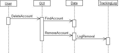
After doing this diagram and looking back at the requirements, we may discover that we have missed some requirements. That will cause us to rework the sequence diagram, perhaps even adding methods to objects. For example, let's say that we realize we forgot the requirement to log any account deletion so we know who performed the action. We might revise our sequence diagram to be:
Sequence diagrams force you to think about the interaction between objects and allow you to find errors before writing code. They are typically used for larger projects.
Next week we will look at how to use classes in C++.